7 Stable operation the power system
We are a guarantor of security and stability of the power system in Poland.
We feel responsible for the security of future generations.
Being aware of the condition of national infrastructure, challenges and trends that affect the development of the system, we perform upgrade work and new investment projects in order to ensure its stability and security.
We want to strengthen awareness and educate society in the field of power market operation.
Key figures

Net national electricity production in 2016,
including 132.4 TWh from non-renewable sources
and 21.7 TWh from renewable sources.

Quantity of electricity supplied from the transmission network to domestic customers of transmission services in 2016.

installed capacity in the PPS in 2016.

maximum capacity in 2016.

Maximum power demand in the PPS in 2016.

Electricity supply continuity index in 2015-2016. Its level confirms the certainty of power supply to all our customers of transmission services.

The low indicators in 2016 testify to a high level of dependability of the transmission system and certainty of power supply to consumers connected to our network.

Availability index for transmission facilities (DYSU). It reached a high value at reference value of ≥ 97.5 percent; in 2015 it reached 99.44 percent.

Capital expenditure in 2016.

Number of infrastructure projects completed in 2016.

Capital expenditure planned until 2021.
Stable operation of the power system
Management of the power system in Poland
How does the power system work?
In terms of the character of its technical functions, the Polish Power System (PPS) consists of three subsystems:
- electricity generation in power plants, CHP plants and distributed sources,
- electricity transmission – a task performed by the transmission system operator,
- distribution and consumption of electricity.
A power system operates in every country of the world. Everywhere it belongs to a particularly guarded type of infrastructure – critical infrastructure. It is of fundamental significance to the functioning of society, the economy and the state. Power systems are controlled centrally almost everywhere, also in Poland.
Operation of the Polish Power System is controlled by the National Power Dispatch Centre.
KSE Energy sources in the Polish Power System
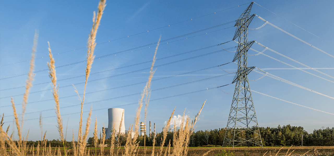
Electricity supplied to our homes is generated mainly in power plants and combined heat and power (CHP) plants. In Poland, the basic energy generating sources are thermal power plants in which energy is generated as a result of combustion – usually by burning hard coal or lignite. The largest cluster of those plants is situated in the southern part of the country. In larger cities, CHP plants operate which are mostly fired with coal, but also natural gas. Renewable energy sources (RES) are also developing: wind, hydro, biomass and photovoltaic.
Go to the detailed description
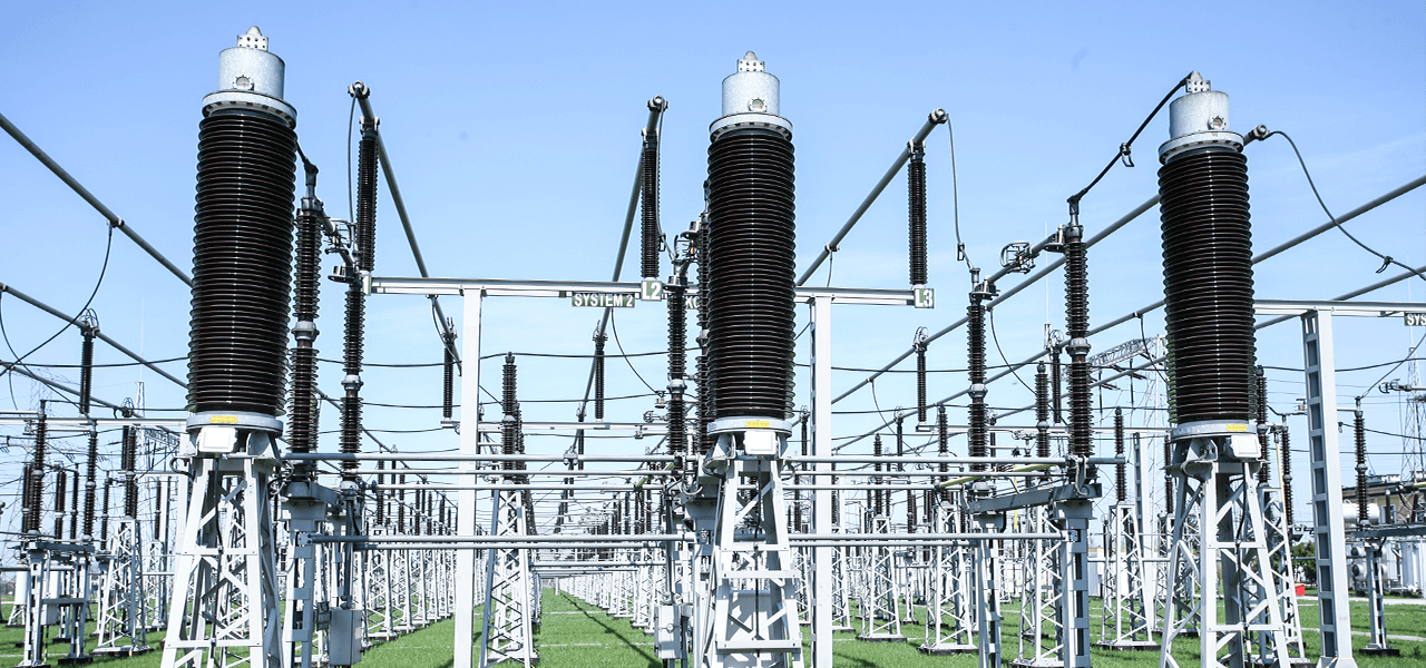
Electricity transmission and distribution
Electricity transmission from power plants to consumers is possible over an extensive network of power lines and electrical substations. Depending on the distance over which electricity is transmitted, different voltage levels are used to optimise costs.
The following voltage standards are adopted in Poland for electricity transmission
- 220, 400, 750 kV (extra-high voltages) – for long-distance transmission,
- 110 kV (high voltage) – for transmission over distances not exceeding several dozens of kilometres,
- 6, 10, 15, 20 or 30 kV (medium voltage) – used in local distribution networks,
- 400/230 V (low voltage) – used basically to supply power to end consumers.
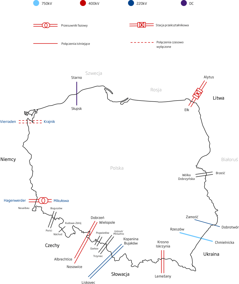
Cross-border interconnections
The Polish Power System operates:
synchronously
with the ENTSO-E
Continental Europe countries (formerly UCTE),
synchronously
with off-grid units
of the Dobrotvir power plant in the Ukrainian system,
asynchronously
with the Swedish system
via the DC submarine cable,
asynchronously
with the Lithuanian system
via the back-to-back DC link.
Synchronous profile
Western border (Poland-Germany)
- 400 kV Krajnik-Vierraden double-circuit line – line under upgrading,
- 400 kV Mikułowa-Hagenwerder double-circuit line with a phase shifter in Mikułowa.
Southern border (Poland-Czech Republic)
- 400 kV Wielopole/Dobrzeń-Nosovice/Albrechtice double-circuit line,
- 220 kV Kopanina/Bujaków-Liskovec double-circuit line.
Southern border (Poland-Slovakia)
- 400 kV Krosno Iskrzynia-Lemesany double-circuit line.
Asynchronous interconnections
Northern border (Poland-Sweden)
- 450 kV DC Słupsk Wierzbięcino-Storno cable line with a capacity of 600 MW.
Eastern border (Poland-Lithuania)
- 400 kV double-circuit line interconnected with the Lithuanian system via the back-to-back DC link with a capacity of 500 MW.
Remaining interconnections
Eastern border (Poland-Ukraine)
- 220 kV Zamość-Dobrotvir single-circuit line operating in coordination with off-grid generating units on the Ukrainian side (the interconnection allows only electricity import to Poland). In September 2011, we started the process allocating transmission capacity of the interconnection through unilateral explicit auctions,
- The 750 kV Rzeszów-Chmielnicka single-circuit line is temporarily shut down. Re-commissioning of the line is being considered after the future character of its operation is agreed with the Ukrainian side.
Cross-border interconnections
Western border (Poland-Germany)
400 kV Krajnik-Vierraden double-circuit line – line under upgrading,
400 kV Mikułowa-Hagenwerder double-circuit line with a phase shifter in Mikułowa.
Southern border (Poland-Czech Republic)
400 kV Wielopole/Dobrzeń-Nosovice/Albrechtice double-circuit line,
220 kV Kopanina/Bujaków-Liskovec double-circuit line.
Southern border (Poland-Slovakia)
400 kV Krosno Iskrzynia-Lemesany double-circuit line.
Eastern border (Poland-Ukraine)
220 kV Zamość-Dobrotvir single-circuit line operating in coordination with off-grid generating units on the Ukrainian side (the interconnection allows only electricity import to Poland). In September 2011, we started the process allocating transmission capacity of the interconnection through unilateral explicit auctions,
The 750 kV Rzeszów-Chmielnicka single-circuit line is temporarily shut down. Re-commissioning of the line is being considered after the future character of its operation is agreed with the Ukrainian side.
Eastern border (Poland-Lithuania)
400 kV double-circuit line interconnected with the Lithuanian system via the back-to-back DC link with a capacity of 500 MW.
Northern border (Poland-Sweden)
450 kV DC Słupsk Wierzbięcino-Storno cable line with a capacity of 600 MW.
Transmission system management in the PPS
Transmission network operation management takes into account the needs of electricity consumers throughout the country
Network operation management is the responsibility of:
- transmission system operator (TSO) – responsible for operation management of the transmission network and exercises decision-making rights relating to network operation in a coordinated 110 kV network, and relating to security of electricity supply,
- distribution system operator (DSO) – responsible for network operation management in the distribution network, for which it is the operator, taking into account the TSO's decision-making rights.
The parties participating in network operation management in a meshed network include also generators, consumers, transmission and distribution undertakings other than system operators, whose devices, facilities or networks are directly connected to a meshed network.
Meshed network includes a TSO-managed transmission network and a DSO-managed coordinated 110 kV network, with the TSO's decision-making rights.
Day-to-day power network security is ensured by hierarchically organised TSO and DSO dispatch services as well as generators' and consumers' O&M services.
Polish Power System is organised into the following hierarchy of dispatch services:
- National Power Dispatch Centre (Krajowa Dyspozycja Mocy – KDM) – manages the operation of the 750, 400, 220 kV transmission network as well as selected 110 kV lines of system-wide significance.
- Area Power Dispatch Centre (Obszarowa Dyspozycja Mocy – ODM) – manages the operation of the transmission network and switching operations of the 750, 400, 220 and 110 kV transmission network.
- Central Power Dispatch Centres, Branch Dispatch Centres (CDM, OCD) – manage the operation of the 110 kV distribution network and switching operations in the 110 kV and lower-voltage distribution network.
The TSO dispatch services cooperate directly with the DSO dispatch services (Central Power Dispatch Centres, Branch Dispatch Centres), O&M personnel of enterprises dealing with electricity generation (Duty Power Plant Operation Engineer - Dyżurny Inżynier Ruchu Elektrowni – DIRE). The cooperation is based on the Transmission Network Code.

Organisation of dispatching services in Poland

TSO Operation & Maintenance services

The TSO's cooperation with transmission system operators of neighbouring countries in network operation management is based on the rules described in ENTSO-E/UCTE Operation Handbook and conditions laid down in bilateral agreements.
Balancing power demand in the power system
GRI 103 Economic development of the country is associated with an increase of electricity demand. This makes it necessary to have appropriate generating and transmission capacity to ensure the security of supply.
In order to ensure generating capacity necessary to meet demand, we perform, as transmission system operator, the coordination planning process for different time horizons. The process covers annual, monthly and daily coordination plans.
Coordination plans are prepared in the form of
Annual plans (PKR)
For a period of up to 3 years
Monthly plans (PKM)
Daily plans
- Preliminary daily plans (WPKD)
- Daily plans (PKD)
- Current daily plans (BPKD)
- Daily technical-trading balances (BTHD)
The schedule of planning activities and the scope of forecasted and published data are set forth in the Transmission Network Code.
The plans should ensure the maintenance of surplus power levels required in a given period, available in excess of forecasted demand, by coordinating plans of generating unit repairs and outages of meshed network elements, taking into account plant and network constraints and planned cross-border exchange constraints.
In order to ensure the continuity of electricity supply and balance the system even in unfavourable conditions,
in periods of peak electricity demand we use:
available capacity
of generating units
which are not centrally dispatched,
additional capacity
in power plants operating in overload
i.e. at a capacity higher than nominal (providing ancillary services),
intervention power supply from pumped storage plants
which allow power demand to be balanced (as part of ancillary services) within a short period (2-4 hours),
dispatch electricity exchange
with the neighbouring transmission system operators,
cold intervention reserve
DSR services
Ancillary services market
In order to perform tasks involved in ensuring the current operational security the power system, we enter into the Ancillary Service Agreements (hereinafter: agreements) with generators dispatching generating units.
This way, we gain access to the unit commitment service and regulation ancillary services which include:
- operating power reserve,
- share in primary control,
- share in secondary control,
- underload or overload operation,
- and participation in automatic voltage and reactive power regulation.
The services are provided by generators under agreements concluded and on the terms and conditions set forth in the Transmission Network Code IRiESP. The agreements are made for each calendar year.
In order to ensure relevant standards if power system operation quality and dependability, the following agreements are concluded:
- for reliability-must-run services (RMR agreements) ensuring volumes of electricity generation by the units involved as required for the proper operation of the PPS,
- for the provision of the contingency operation service ensuring access to rapid intervention reserve.

DSR Intervention Programmes
In fulfilling our primary role – ensuring the secure operation of the power system – we carry on work at the development and implementation of mechanisms that improve the security of power system operation.
One of such mechanisms is the development and implementation of the rules of power demand reduction in the PPS in periods of supply-demand imbalance in the PPS. For example, in periods of very high demand in the PPS in where it is not possible to meet the demand while ensuring an appropriate generating capacity reserve.
We continue work towards creating conditions for the acquisition of an additional capacity volume for the provision of the interruptible load service to the TSO, known as the DSR service.
The DSR service involves the reduction of energy consumption by consumers in periods of peak demand of the Polish Power System, and it is one of the tools used to ensure operation security of the PPS. We have prepared new DSR (Demand Side Response) Intervention Programmes.
Our activities completed in 2016
We have developed a new concept of DSR Intervention Programmes, in which we have defined the rules for the provision of the DSR service.
- It can be provided by an consumer with the capability to shed loads connected to voltages above 1 kV.
- It can be provided by reduction facilities (ORed) duly certified by the operator of the transmission system to which the ORed concerned is connected.
- Depending on the reduction potential, the consumer may enter into an agreement directly with PSE or with an aggregator who will represent it in relations with our company.
- It can be provided under two programmes: guaranteed and current.
Based on the concept of DSR Intervention Programmes (IP-DSR), Transmission Network Code Revision Sheet No CB/16/2016 was developed and implemented, which defined two DRS intervention programmes.
Guaranteed programme
With payment for readiness to provide the DSR service and for reduction effected with a reduction volume contractually guaranteed by the service provider.
Current programme
With payment for reduction effected in the absence of a reduction volume contractually guaranteed by the service provider.
Our activities taken up in 2017
Based on the DSR III concept, Transmission Network Code (IRIESP) Revision Sheet No CB/17/2017 governing the rules for:
- certification of reduction facilities (ORed),
- using the DSR service in a period of restrictions on electricity supply and consumption.
Promptly after the entry into force of Transmission Network Code (IRIESP) Revision Sheet IRIESP No CB/17/2017, we started the process of certifying reduction facilities (OReds) connected to the transmission network and coordinated the certification process for the reduction facilities connected to the distribution network.
In parallel with the measures described above, we have implemented IT systems that support the management of the DSR service and the process of certification and acquisition of metering/billing data.
In the first half of 2017, we conducted a tendering procedure for the interruptible load service on instructions from the TSO. Consequently, we have acquired nine contractors for the DSR service under the guaranteed programme (with a total reduction capacity of 361 MW in summer and 315 MW in winter) and five contractors under the current programme. Most importantly, we have signed agreements with all contractors selected through a tendering procedure for the provision of the interruptible load service on instructions from the TSO.
Security and continuity of supply
System operation dependability indicators
GRI EU28, GRI EU29 Indicators that characterise the continuity of supply and duration of outages (ENS and AIT) have been calculated for a group of supply sites comprising final consumers and power distribution system operators who have one transmission network supply site. Shutting down the supply site practically results in interruption of electricity supply from the transmission network to consumers fed from that network.
ENS, AIT indicators for emergency shutdowns
ENS

AIT

*The values of the ENS and AIT indicators presented in the table have been calculated for unscheduled (emergency) outages and do not include scheduled outages.
Low levels of the ENS and AIT indicators testify to a high level of operational dependability of the transmission system and the certainty of supply to consumers connected to the network. In 2016, no emergency outages occurred, whereas in 2015 there was only one such outage, which resulted to a short interruption (only 3 minutes) of power supply to one of consumers fed from the transmission network.
ENS and AIT indicators for all outages (planned and emergency)
ENS

AIT

ENS
An indicator of electrical Energy Not Supplied by the power transmission system. It is expressed in MWh per year and represents a sum of products of power not supplied due to interruption and its duration. The indicator includes short, long and very long interruptions including and excluding disastrous interruptions.
AIT
An indicator of Average Interruption Time in the power transmission system. Expressed in minutes per year, it is a product of 60 and energy not supplied (ENS) by the power system, divided by the average power supplied by the transmission system, expressed in MW.
*The ENS and AIT values have been calculated for emergency and scheduled outages resulting from necessary scheduled repair and maintenance work on transmission network elements feeding consumers.
In the case of scheduled outages, shutdowns are performed at times agreed with consumers, usually in declared outage periods, whereby consumers adjust their demand in outage periods or use other methods electricity supply (e.g. from the DSO network).
The ENS and AIT values remaining at a steady low level (the 20016 values were similar to those reported in the previous year) has a positive effect on the confidence of consumers connected to the transmission network. We reduce the number and duration of interruptions in electricity supply to consumers due to scheduled outages by implementing systems optimising the schedule of repair and maintenance work on transmission network elements feeding consumers.
Electricity supply continuity index
The supply continuity index represents the certainty of power supply to all consumers connected to the transmission network
in 2015 and 2016
WCD
The indicator is calculated as the total quantity of electrical energy delivered to transmission service customers (DSOs and final consumers) divided by the sum of the quantity of electrical energy supplied and not supplied to those consumers during a year.
The quantity of electrical energy not supplied to transmission service customers in a year has been calculated taking into account both scheduled and unscheduled cuts in electricity supply to consumers. The use of the indicator of total quantity of electrical energy supplied from the transmission network during a year represents the volume of electricity taken from the transmission network at all supply sites by final consumers and distribution system operators connected to the transmission network.
| GRI EU12 Transmission losses as percentage of total energy taken off | Unit | 2016 | 2015 |
|---|---|---|---|
|
Electrical energy losses in the transmission process, showing loss causes |
|||
| - technical losses | MWh | 1 684 995 | 1 832 858 |
| - non-technical losses (e.g. illegal consumption of electricity) | MWh | 0 | 0 |
| Transmission losses as percentage of total energy fed into the system (G.10.7 official data)* | % | 1,62 | 1,77 |
*The value does not include energy consumed by substation auxiliaries.
Technical transmission losses are related, among other things, to network operational configuration, electricity demand and the quantity of electricity transmitted in cross-border exchange.
Development of the transmission system
GRI 103 The provision of the necessary quantity of electricity to all consumers is key to ensuring sustainable development of the national economy. We seek to ensure that the transmission system provides dependable electricity supply both today and in the future. It is our responsibility.
Our investment plans
We plan the development of the transmission system in the long, mid and short term.
For this purpose, we develop, implement and improve the following plans:
- transmission network development plan – a long-term plan,
- investment projects plan,
- tangible investment plan.

Transmission network development plan (PRSP)
The PRSP plan is based on the provisions of the Energy Law. The document takes into account the National Spatial Development Concept and the assumptions of the Energy Policy of Poland. It is created for 10 years and updated every 3 years. The document is coordinated with the President of ERO. It is also subject to consultations with the parties concerned, including opinions of regional government bodies – Marshal's Offices.
The plan sets forth the development transmission network development projects which, when completed, are expected to meet national power and energy demand. The main factors affecting the direction of its development include: growth of electricity demand, development of generating sources and the need to expand cross-border interconnections.
In the reporting period, we implement the Development Plan for meeting the current and future electricity demand for 2016-2025 agreed with the President of ERO for the years 2016-2018. It includes 151 projects involving construction, expansion and upgrades of substations and power lines.
Go to the Development Plan
The total capital expenditure planned to be incurred by 2025 amounts to approx. PLN 13.3 bn.
The main objectives of the projects contained in the development plan concern
Improvement of the security of electricity supply
Connection
and evacuation of power
from off-shore wind farms
Connection
and evacuation of power
from new baseload power plants
Cross-border interconnections
The quantitative scope of the Development Plan provides for the implementation over a ten-year period of investment projects involving the construction of 9 new substation facilities, expansion of 39 existing substations and upgrades of 23 existing substations and switchyards. With regard to transmission lines, construction of about 4,300 km new current paths and upgrades of almost 2270 km of existing 400 i 220 kV lines is planned.
In 2017, the Company prepared and submitted to the President of the Energy Regulatory Office a Report on the implementation in 2016 of the Plan for the Years 2016-2025.
In 2016, 14 investment projects were completed:
- Construction of the 400 kV line from Dobrzeń to the Pasikurowice – Wrocław line tap
- Installation of phase shifting transformers on the 400 kV Mikułowa – Hagenwerder line
- Construction of the 220 kV line from Stalowa Wola to the Chmielów – Abramowice line tap
- Upgrade of the 220 kV Morzyczyn-Police line – Stage I
- Upgrade of existing and installation of new optical ground wires (OPGW) on selected 220 kV and 400 kV lines - Stage I (Package I)
- Upgrade of the 220 kV Stalowa Wola – Chmielów line (OPGW)
- 220/110kV Gorzów substation for the connection of the CHP Plant Gorzów CCGT unit
- Expansion of 110 kV switchgear at the 220/110 kV Adamów substation for industrial gas plant connection
- Expansion of the 400 kV Stanisławów substation for the connection of the Korytnica WF
- Expansion of the 110 kV switchgear at the 220/110 kV Piła Krzewina substation for the connection of the Krzewina and Chwiram wind farms
- Upgrade of the 400/220/110 kV Miłosna and 400/220/110 kV Kozienice substations by adding redundant busbar protection
- Installation of an automatic load shedding system at the 400/220/110 kV Połaniec substation
- Upgrade of the transformer population - Stage III
- Deployment of the Technical Protection Systems for the substations: Boguszów, Katowice, Kielce, Ostrów, Piaseczno, Tarnów, as well as the ODM Bydgoszcz and ODM Katowice dispatch centres
The PRSP 2016-2025 plan includes all investment projects within the territory of Poland provided for in the Ten-Year Network Development Plan (TYNDP 2016).
Community-wide Ten-Year Network Development Plan
In fulfilment of the obligation arising from the provisions of Regulation 714/2009, every other year ENTSO-E publishes a Community-wide Ten-Year Network Development Plan (TYNDP). The latest edition of the plan was published in December 2016.
The main aim of the projects covered by TYNDP 2016 is to achieve European energy objectives, such:
- security of supply,
- sustainable development of the power system,
- creating conditions for the functioning of the European electricity market.
The development needs in the European power system identified during analyses conducted in the process of creating TYNDP 2016 arise, among other things, from the growing installed capacity at renewable energy sources, mainly wind farms, and elimination of “energy islands”.
TYNDP 2016 provides for three clusters of projects concerning the national development of the transmission network and cross-border interconnections
Cluster 1 – Project 94 GerPol Improvements
The objective of the project is to increase cross-border transmission capacity on synchronous profile (including connections on the border with Germany, Czech Republic and Slovakia) by upgrading the Krajnik-Vierraden 220 kV line to 400 kV and installing phase shifting transformers on the existing Poland-Germany interconnection lines. The project is implemented jointly by PSE and the German operator 50Hertz.
Cluster 2 – Project 230 GerPol Power Bridge I
The objective of the project is to further increase cross-border transmission capacity on the synchronous profile. The project will be implemented in two stages. At the first stage, by 2021, expansion of the internal transmission network is planned in the western part of the country.
Cluster 3 – Project 123 LitPol Link Stage II
The LitPol Link Stage II project is a continuation of construction of an interconnection between Poland and Lithuania aimed to achieve a planned transmission capacity of 1000 MW in both directions. To implement the second stage of the project, it is necessary to build additional transmission network facilities in Poland and in Lithuania, including the second back-to-back DC link at the Alytus substation.

Investment Projects Plan
The Investment Projects Plan (hereinafter: PZI) is a medium-term plan which is updated annually through the rolling wave planning process for the next 5 years. It is a refinement of the Transmission Network Development Plan (hereinafter: PRSP). The objective of PZI is to coordinate network investments in physical, time and financial terms, in line with long-term directions set in PRSP. The first PZI planning year is represented by the Tangible Investment Plan (TIR) which is a basis for operational monitoring and reporting capex performance in the first planning year (n+1).
According to the new Project Implementation Model implemented at PSE, we have deployed a tool for the management of the network project implementation process – Network Investment Portfolio. The first portfolio is based on an update of the PSE Investment Projects Plan for 2017-2021 approved by the Supervisory Board of PSE. The projects included in the portfolio are grouped, categorised, prioritised and sequenced for implementation taking into account specific system conditions related to the possibility of required outages of network elements. The portfolio is subject to quarterly updates, and it is accepted in each case by the Investment Committee. It then becomes an input for the preparation of PZI for the next planning period.
The Network Investment Portfolio consists of transmission network construction, expansion and upgrade projects for which:
- agreements have been signed with contractors,
- the public contract notice has been published,
- the contract award decision has been made.
Owing to functional interrelations and a common objective of certain investment projects, the projects included in the Network Investment Portfolio have been grouped into investment programmes so as to allow each programme to be assigned a separate meaning reflecting its role in the system and the expected outcome. Projects have been grouped into programmes taking into account the results of system analyses performed at the stage of scoring analysis of investment projects and tasks included in the Investment Projects Plan of PSE S.A. 2017-2021. This way, 5 strategic programmes and 3 area programmes have been created.
Strategic programmes for 2017-2021
Programme 1.
Power evacuation from Kozienice Power Plant including the improvement of power supply conditions in north-eastern Poland: 14 projects, PLN 0.83 bn of total contracted budget as at 31 October 2017.
Programme 2.
Power evacuation from Turów Power Plant including the improvement of power supply conditions in south-eastern Poland: 12 projects, PLN 0.79 bn of total contracted budget as at 31 October 2017.
Programme 3.
Power evacuation from Dolna Odra Power Plant and RES including the improvement of power supply conditions in north-western Poland: 11 projects, PLN 1.11 bn of total contracted budget as at 31 October 2017.
Programme 4.
Power evacuation from RES including the improvement of power supply conditions in northern Poland: 14 projects, PLN 2.15 bn of total contracted budget as at 31 October 2017.
Programme 5.
Power evacuation from Bełchatów Power Plant including the improvement of power supply conditions in central Poland:
4 projects, PLN 0.15 bn of total contracted budget as at 31 October 2017.
Area Programmes for 2017-2021
Programme 6.
Area Programme North: 23 projects, PLN 0.77 bn of total contracted budget as at 31 October 2017.
Programme 7.
Area Programme South: 39 projects, PLN 1.17 bn of total contracted budget as at 31 October 2017.
Programme 8.
Formal completion of investment projects: 25 projects, PLN 3.18 bn of total contracted budget as at 31 October 2017.
Programme 3
Power evacuation from Dolna Odra Power Plant and RES including the improvement of power supply conditions in north-western Poland: 11 projects, PLN 1.11 bn of total contracted budget as at 31 October 2017.
Programme 4
Power evacuation from RES including the improvement of power supply conditions in northern Poland: 14 projects, PLN 2.15 bn of total contracted budget as at 31 October 2017.
Programme 1
Power evacuation from Kozienice Power Plant including the improvement of power supply conditions in north-eastern Poland: 14 projects, PLN 0.83 bn of total contracted budget as at 31 October 2017.
Programme 5
Power evacuation from Bełchatów Power Plant including the improvement of power supply conditions in central Poland: 4 projects, PLN 0.15 bn of total contracted budget as at 31 October 2017.
Programme 2
Power evacuation from Turów Power Plant including the improvement of power supply conditions in south-eastern Poland: 12 projects, PLN 0.79 bn of total contracted budget as at 31 October 2017.
Programme 6
Area Programme North: 23 projects, PLN 0.77 bn of total contracted budget as at 31 October 2017.
Programme 7
Area Programme South: 39 projects, PLN 1.17 bn of total contracted budget as at 31 October 2017.
Programme 8
Formal completion of investment projects: 25 projects, PLN 3.18 bn of total contracted budget as at 31 October 2017.

Key figures

projects under strategic and area programmes – 29 before contracting, 113 after contracting

total contracted budget for projects under the Network Investment Portfolio
Implementation of the Tangible Investment Plan
GRI 203-1 We create strategic and area programmes and select a package of investment projects for them to ensure the effective performance of strategic objectives based on sustainable development of the national transmission system. In doing so, we take into account the current conditions – especially system and formal/legal conditions of project implementation.
Formalities and legal issues related to line construction projects take 80 percent of the contract time, whereas the line construction phase itself accounts for no more than 20 percent.
Capital expenditure by Plan group (amounts)
|
Description |
Capex [PLN bn] | |
|---|---|---|
|
2016 |
2015 | |
|
ICT |
37,3 |
28,9 |
|
Construction and expansion of power lines and substations |
1 024,3 |
1 277,1 |
|
Upgrade of substations and power lines |
136,5 |
208,4 |
|
Buildings and structures |
1,8 |
1,2 |
|
Purchase of finished capital goods |
4,4 |
5,9 |
|
Preparation of investment projects |
8,9 |
8,4 |
|
Purchase of network facilities |
3,7 |
6,0 |
|
Total |
1 216,9 |
1 535,9 |
Investment projects in progress
|
Description |
Number of tasks | |
|---|---|---|
|
2016 |
2015 | |
|
Continued tasks |
107 |
102 |
|
Newly started tasks |
20 |
22 |
|
TOTAL |
127 |
124 |
GRI 203-2 The investment projects involving the highest capital expenditure include.
- Construction of the 400 kV Kozienice-Siedlce Ujrzanów line
- Construction of the 400 kV Ostrołęka-Olsztyn Mątki line
- Construction of the 400 kV line from Dobrzeń to the Pasikurowice-Wrocław line tap
- Expansion and upgrade of the Byczyna substation with the 400 kV Tucznawa-Tarnów line entry
- Construction of the 400(220)/110kV Pelplin substation including 220/110 kV transformer installation
- Installation of phase shifting transformers on the 400 kV Mikułowa - Hagenwerder line
- Construction of the 400 kV Gdańsk Przyjaźń-Żydowo Kierzkowo line
- Expansion of the 400/110 kV Dobrzeń substation
- Expansion of the 400/110 kV Płock substation
- Upgrade of the transformer population - Stage V
- Expansion and upgrade of the 400/220/110 kV Kozienice substation with regard to 400 kV switchgear
- Expansion and upgrade of the 400/220/110 kV Mikułowa substation
- Expansion of the 220/110 kV Skawina substation by adding the 400 kV and 110 kV switchgears
- Extension and upgrade of the 400/220 kV Krajnik substation
- Expansion of the 220/110 kV Kielce Piaski substation
- Construction of the 400/110 kV Żydowo Kierzkowo substation including 220/110 kV transformer installation
- Upgrade of existing and installation of new optical ground wires (OPGW) on selected 220 kV and 400 kV lines
Non-financial outcomes of completed investment projects in the form of fixed assets and intangible assets were transferred to fixed assets of PSE. They concerned, among other things, the projects mentioned below.
- Construction of the 400 kV line from Dobrzeń to the Pasikurowice-Wrocław line tap
- Installation of phase shifting transformers on the 400 kV Mikułowa - Hagenwerder line
- Expansion of the 220/110 kV Skawina substation by adding the 400 kV and 110 kV switchgears
- Construction of the 220 kV line from Stalowa Wola to the Chmielów – Abramowice line tap
- Upgrade of existing and installation of new optical ground wires (OPGW) on selected 220 kV and 400 kV lines

total capital expenditure incurred for the implementation of investment projects and plans

total value of tangible and intangible assets transferred to fixed assets of PSE

Maintaining the transmission network
We are the owner of a transmission network consisting of over 14,000 km of extra-high voltage lines and 106 electrical substations. The availability of our network largely determines the operational security of the whole system. Therefore, we maintain the transmission network in a state of repair and operational setup meeting the applicable requirements.
We have the following equipment installed at the substations
- 2 x 750/400 kV transformers with a total capacity of 2,500 MVA
- 25 x 400/220 kV transformers with a total capacity of 11,320 MVA
- 52 x 400/110 kV transformers with a total capacity of 15,920 MVA
- 118 x 220/110kV autotransformers with a total capacity of 19,785 MVA
- 1 x 400/450 kV transformer with a capacity of 708 MVA
- 4 phase shifting transformers with a total capacity of 4,800 MVA
- 7 reactors with a total capacity of 1,080 Mvar
Our network infrastructure also includes a 450 kV submarine cable line of 127 km in length. The length of the entire line connecting Poland with Sweden is 254 km.
| GRI-EU4 Length* and number of above-ground power transmission lines | |||||
|---|---|---|---|---|---|
| 2016 |
2015 |
||||
| Overhead (above-ground) lines | |||||
| Voltage | Length (in km) converted to 1 circuit: | Number | Voltage | Length (in km) converter to 1 circuit: | Number |
| 750 kV | 114 km | 1 | 750 kV | 114 km | 1 |
| 400 kV | 6139 km | 90 | 400 kV | 5984 km | 89 |
| 220 kV | 7870 km | 165 | 220 kV | 7970 km | 167 |
| 110 kV | 72 km | 33 | 110 kV | 72 km | 33 |
*Line length converted to 1 circuit.
| GRI-EU4 Length* and number of underground power transmission lines | |||||
|---|---|---|---|---|---|
| 2016 | 2015 |
||||
| Cable lines (underground) | |||||
| Voltage | Length (in km) converted to 1 circuit: | Number | Voltage | Length (in km) converted to 1 circuit: | Number |
| 450 kV DC | submarine 450 kV DC Poland – Sweden link with a total length of 254 km (of which 127 km belongs to PSE) | 1 | 450 kV DC | submarine 450 kV DC Poland – Sweden link with a total length of 254 km (of which 127 km belongs to PSE) | 1 |
| 220 kV | 3 km – the length of cable sections of the 3 overhead and cable lines included above | - | 220 kV | 1 km – the length of a cable section of the overhead and cable line included above | - |
| 110 kV | 2 km – the length of cable sections of the 2 overhead and cable lines included above | - | 110 kV | 2 km – the length of cable sections of the 2 overhead and cable lines included above | - |
*Line length converted to 1 circuit.
The condition of the transmission network is confirmed by a high collective transmission equipment availability factor (DYSU) which reached 99.74 percent in 2016 compared with 99.44 in 2015.
| Transmission equipment availability factor [DYSU] | I-XII 2016 [%] | Reference value of the transmission equipment availability factor |
|---|---|---|
| Category L1 transmission line availability factor [DL1] | 99,64 | |
| Category L2 transmission line availability factor [DL2] | 99,63 | |
| Generator outgoing line availability factor [DLB] | 99,99 | |
| Transformer availability factor for Category S11 substations [DS11] | 99,85 | |
| Transformer availability factor for Category S22 substations [DS22] | 99,59 | |
| DYSU | 99,74 | ≥ 97,5 |
The transmission equipment availability factor – DYSU – is calculated as the arithmetical average of availability factors for 5 groups of transmission equipment including groups of lines and transformers installed at our substations.
The availability of each of those equipment groups is calculated as the ratio of the actual working time of transmission equipment (in hours) during a year to the nominal number of hours in a year.
The DYSU factor is designed to monitor the readiness of transmission elements to provide the electricity transmission service. The factor takes into account the availability of the following 5 groups of transmission equipment.
1. Category L1 lines
2. Category L2 lines
3. Category LB generator outgoing lines
4. Transformers at Category S11 substations
5. Transformers at Category S22 substations
| Legal status of our electrical substations | Area (IN m2) |
|---|---|
| Ownership | 2 272 688 |
| Joint ownership | 2 803 |
| Perpetual usufruct right | 5 280 634 |
| Share in perpetual usufruct right | 3 329 |
| Right of possession | 881 |
| Total: | 7 560 335 |
| Communication and IT assets (forming part of the network infrastructure) | Number |
|---|---|
| Telecommunication lines (including optical fibres as components of power lines) |
362 |
| IT hardware | 9 892 |
| Signal transmission and telecommunication devices | 3 085 |
| Devices forming part of power supply systems and air-conditioning systems and measuring instruments | 1 480 |
| Licences, copyrights and proprietary rights | 2 632 |
Management of the network maintenance process
The maintenance of our network infrastructure is based on the grid asset maintenance model. The model is a set of overriding principles that govern the process of grid asset maintenance in the area of organisation, planning, execution, documentation and billing of maintenance work.
It defines the scopes of work and the rules for the performance of work with reference to laws and regulations as well as statutory obligations imposed on the transmission system operator. Hence it creates conditions for the systematic execution of the optimisation process with regard to the maintenance of grid assets.
Arising directly from the maintenance model are detailed rules for equipment maintenance put together in the Instruction on the Organisation and Execution of Maintenance Work on EHV Lines and Substations, as well as the guidelines on the assessment of the state of repair and the Repair Qualification Model.
We have updated the asset maintenance model based on our previous experience. We have opted out of the Time-Based Maintenance (TBM) process which is based on fixed work cycles resulting directly from O&M manuals of individual equipment units. The new asset maintenance model falls in line with the Reliability Centred Maintenance (RCM) model – it combines regular measurements of the state of repair taking into account expected quality outcomes of their work (diagnostics results). The main focus is placed on diagnostic work providing a basis for a measurable result of the state of repair of individual pieces of network equipment.
The outcomes of the work concerned, combined with the experience gained through many years of maintenance of equipment make it possible to assess the state of repair of equipment units and forecast the rate of their deterioration, and consequently to identify the impact of maintenance (inspections, maintenance procedures) on the condition of such equipment in the future. At the same time, the maintenance model makes it possible to forecast the cost of maintenance of individual equipment units throughout their service life.
In the network maintenance process, we use the Asset Management IT process. It covers the entire maintenance process, i.e. a complex database of assets, registration of events, work planning and execution, contract management and warehouse management.
What is more, the maintenance process is supported by the following systems
- The remote supervision and control system (SSiN) providing data on network parameters and the state of repair of individual network elements.
- Spatial Information System.
Advantages arising from the use of the systems presented
- The ability to control the life cycle of individual network elements.
- Current information on the location of network elements and their environment in terms of infrastructure and ownership.
- Adjustment of the organisation of grid asset management at strategic and operational level to a complete, fully functional system of remote monitoring, supervision and control of transmission system operation without permanent substation operation personnel.
Implementing new diagnostic methods, gradual digitisation of the grid asset maintenance process, and a high and continuously developed competence level of personnel performing maintenance tasks, we seek – in accordance with the lean management concept – to achieve an even greater operational dependability of network elements.


